The Power of Sound
By Steven Garrett, Scott Backhaus
Sound waves in "thermoacoustic" engines and refrigerators can replace the pistons and cranks that are typically built into such machinery
Sound waves in "thermoacoustic" engines and refrigerators can replace the pistons and cranks that are typically built into such machinery

DOI: 10.1511/2000.41.516
Last February, a panel of the National Academy of Engineering announced the results of its effort to rank the greatest engineering achievements of the 20th century. Second and tenth on that list were two very successful heat engines: the automobile (and hence, the internal-combustion engine) and the refrigerator and air conditioner, heat engines operated in reverse.
But these two pillars of modern technology share another, less flattering distinction: Both have inadvertently damaged the environment—by clouding skies with smog, spewing greenhouse gases or leaking compounds that erode the earth's protective blanket of stratospheric ozone.
Adam Woolfitt/Corbis.
Over the past two decades, investigators like ourselves have worked to develop an entirely new class of engines and refrigerators that may help reduce or eliminate such threats. These thermoacoustic devices produce or absorb sound power, rather than the "shaft power" characteristic of rotating machinery. Because of its inherent mechanical simplicity, such equipment may one day serve widely, perhaps generating electricity at individual homes, while producing domestic hot water and providing space heating or cooling.
How do these machines work? In a nutshell, a thermoacoustic engine converts heat from a high-temperature source into acoustic power while rejecting waste heat to a low-temperature sink. A thermoacoustic refrigerator does the opposite, using acoustic power to pump heat from a cool source to a hot sink. These devices perform best when they employ noble gases as their thermodynamic working fluids. Unlike the chemicals used in refrigeration over the years, such gases are both nontoxic and environmentally benign. Another appealing feature of thermoacoustics is that one can easily flange an engine onto a refrigerator, creating a heat-powered cooler with no moving parts at all.
So far, most machines of this variety reside in laboratories. But prototype thermoacoustic refrigerators have operated on the Space Shuttle and aboard a Navy warship. And a powerful thermoacoustic engine has recently demonstrated its ability to liquefy natural gas on a commercial scale.
That sound-powered equipment can accomplish these tasks seems almost magical—and rightly so: Arthur C. Clarke once remarked that "any sufficiently developed technology is indistinguishable from magic." Below we attempt to reveal the legerdemain and explain the simple physics that makes thermoacoustic machines possible.
The interaction of heat and sound has interested acousticians since 1816, when Laplace corrected Newton's earlier calculation of the speed of sound in air. Newton had assumed that the expansions and compressions of a sound wave in a gas happen without affecting the temperature. Laplace accounted for the slight variations in temperature that in fact take place, and by doing so he derived the correct speed of sound in air, a value that is 18 percent faster than Newton's estimate.
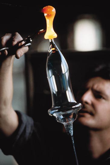
Such thermal effects also explain why 19th-century glassblowers occasionally heard their heated vessels emit pure tones—a hint that thermoacoustics might have some interesting practical consequences. Yet it took more than a century for anyone to recognize the opposite effect: Just as a temperature difference could create sound, sound could produce a temperature difference—hot to one side, cool to the other. How acoustic cooling can arise is, in retrospect, rather easy to understand.
Suppose an acoustic wave excites a gas that was initially at some average temperature and pressure. At any one spot, the temperature will go up as the pressure increases, assuming the rise happens rapidly enough that heat has no time to flow away. The change in temperature that accompanies the acoustic compressions depends on the magnitude of the pressure fluctuations. For ordinary speech, the relative pressure changes are on the order of only one part per million (equivalent to 74 decibels, or dB, in sound pressure levels), and the associated variation in temperature is a mere ten-thousandth of a degree Celsius. Even for sounds at the auditory threshold of pain (120 dB), temperature oscillates up and down by only about 0.02 degree.
Most refrigerators and air conditioners must pump heat over considerably greater temperature ranges, usually 20 degrees or more. So the temperature swings that typical sound waves bring about are too small to be useful. To handle larger temperature spans, the gas must be put in contact with a solid material. Solids have much higher heat capacities per unit volume than gases, so they can exchange a considerable amount of heat without changing in temperature by very much. If a gas carrying a sound wave is placed near a solid surface, the solid will tend to absorb the heat of compression, keeping the temperature stable. The opposite is also true: The solid releases heat when the gas expands, preventing it from cooling down as much as it otherwise would.
The distance over which the diffusion of heat to or from an adjacent solid can take place is called the thermal penetration depth. Its value depends on the frequency of the passing sound wave and the properties of the gas. In typical thermoacoustic devices, and for sound waves in air at audio frequencies, the thermal penetration depth is typically on the order of one-tenth of a millimeter. So to optimize the exchange of heat, the design of a thermoacoustic engine or refrigerator must include a solid with gaps that are about twice this dimension in width, through which a high-amplitude sound wave propagates. The porous solid (frequently a jelly-roll of plastic for refrigerators or of stainless steel for engines), is called a "stack," because it contains many layers and thus resembles a stack of plates.
When an acoustically driven gas moves through the stack, pressure, temperature and position all oscillate with time. If the gas is enclosed within a tube, sound bounces back and forth creating an acoustic standing wave. In that case, pressure will be in phase with displacement—that is, the pressure reaches its maximum or minimum value when the gas is at an extreme of its oscillatory motion.
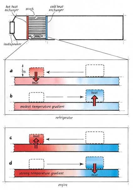
Consider how this simple relation can be put to use in a thermoacoustic refrigerator, which in its most rudimentary form amounts to a closed tube, a porous stack and a source of acoustic energy. As a parcel of gas moves to one side, say to the left, it heats up as the pressure rises and then comes momentarily to rest before reversing direction. Near the end of its motion, the hot gas deposits heat into the stack, which is somewhat cooler. During the next half-cycle, the parcel of gas moves to the right and expands. When it reaches its rightmost extreme, it will be colder than the adjacent portion of the stack and will extract heat from it. The result is that the parcel pumps heat from right to left and can do so even when the left side of the stack is hotter than the right.
The span of movement for an individual parcel is quite small, but the net effect is that of a bucket brigade: Each parcel of oscillating gas takes heat from the one behind and hands this heat off to the next one ahead. The heat, plus the work done to move it thermoacoustically, exits one end of the stack through a hot heat exchanger (similar to a car radiator). A cold heat exchanger, located at the other end of the stack, provides useful cooling to some external heat load.

One can easily reverse this process of refrigeration to make a thermoacoustic engine. Just apply heat at the hot end of the stack and remove it at the cold end, creating a steep temperature gradient. Now when a parcel of gas moves to the left, its pressure and temperature rise as before, but the stack at that point is hotter still. So heat flows from the stack into the gas, causing it to expand thermally just as pressure reaches a maximum. Conversely, when the parcel shifts to the right, it expands and cools, but the stack there is cooler still. So heat flows into the solid from the gas, causing thermal contraction just as pressure reaches a minimum. In this way, the temperature variation imposed on the stack drives heat into and out of the gas, forcing it to do work on its surroundings and amplifying the acoustic oscillations. Maintenance of the steep thermal gradient requires an external source of power, such as an electric heater, concentrated sunlight or a flame—which explains why glassblowers sometimes observe the spontaneous generation of sound when they heat the walls of a glass tube (serving as a stack) in such a way as to create a strong temperature gradient, a phenomenon first documented in a scholarly journal in 1850.
Indeed, this "singing tube" effect arises easily enough that Reh-lin Chen, a student in the Graduate Program in Acoustics at the Pennsylvania State University, was able to build a thermoacoustic engine with only three parts. The stack consists of a plug of porous ceramic (material that is normally used for automotive catalytic converters). Electrical current passing through a heater wire attached at one end of the plug imposes a temperature gradient. A Pyrex test tube acts as a miniature organ pipe and sets up a standing acoustic wave. Because the cold end of the stack faces the mouth of the test tube, no cold heat exchanger is needed: Air streaming in and out of the open end of the tube provides sufficient cooling. Despite its simplicity, Chen's engine is capable of producing sound at uncomfortable levels.
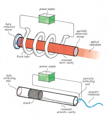
The transparency of this device, literal and figurative, invites analogies with the laser. Borrowing some vocabulary from optics, one would say that a non-equilibrium condition (corresponding to the population inversion of electron energy levels in a laser material) is maintained across the heated stack. The test tube amounts to an acoustic resonator, which, like a laser cavity, allows a standing wave to build in amplitude as energy bounces back and forth. The open side of the test tube serves the same function as the partially silvered mirror at the output side of a laser. Both allow some of the energy stored within the resonant cavity to radiate into the surrounding environment. Although Chen's "acoustic laser" produces only about a watt of sound power, a similar device heated by the burning of natural gas produces in excess of 10 kilowatts—a high-powered laser indeed!
One of the most remarkable features of such thermoacoustic engines is that they have no moving parts. They demand nothing beyond the basic physics of the cavity and stack to force the compressions, expansions, displacements and heat transfers to happen at the right times. The internal-combustion engines in our cars also depend on proper timing—the intake, compression, expansion and exhaust stages of the power cycle must take place in smooth succession. But conventional automobile engines require at least two valves per cylinder, each with a spring, rocker arm and a push rod (or an overhead cam driven by a timing belt) to produce the required phasing. This difference makes thermoacoustic devices much simpler and potentially much more reliable than conventional engines and refrigerators, because they can avoid wear associated with valves, piston rings, crankshafts, connecting rods and so forth. Thus thermoacoustic devices require no lubrication.
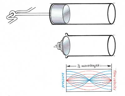
To the uninitiated, it may seem surprising that pistonless engines can achieve high power levels. Thermoacoustic devices manage this feat by exploiting acoustic resonance to produce large pressure oscillations from small gas motions. Consider a closed tube (an acoustic resonator) with a loudspeaker mounted at one end. The oscillating movement of the loudspeaker pumps in acoustic energy, which travels down the tube at the speed of sound, reflects off the far end and shoots back toward the source. If the frequency of the excitation is just right, the next increment of energy that the loudspeaker injects will arrive in step with the reflected portion of the acoustic wave.
The pressure swings in the resonating wave will then grow until the energy added during one cycle is exactly equal to the energy dissipated during one cycle, either by friction or by the production of useful work. The ultimate value of the pressure variation depends on the quality factor of the resonator, Q (which is equal to 2/π times the ratio of the pressure the loudspeaker produces in the resonator to that which the same loudspeaker would have generated in an infinitely long tube, one in which there would be no reflected wave).
The result of this resonant Q amplification can be easily understood by considering the motion of a piston compressing some gas within a cylinder. If the initial length of the gas volume is, say, 20 centimeters and the piston moves slowly inward 1 centimeter, the pressure of the gas would increase by 5 percent, assuming no leakage around the piston. If, however, it oscillated back and forth rapidly at the resonant frequency of the cavity (860 cycles per second, assuming that the cylinder is filled with air at room temperature so that exactly one-half wavelength of sound fits inside), the piston would only have to move by something like 0.05 millimeter in a typical cavity (Q=30) to produce the same change in pressure. That tiny distance is only one two-hundredth as far as in the case of slow compression, yet it achieves exactly the same peak pressure.
Clearly, an oscillating acoustic source that moves such small distances does not need a piston with sealing rings moving in a lubricated cylinder—eliminating all sorts of pesky components found in conventional refrigeration compressors and internal-combustion engines. Flexible seals, such as metal bellows, would suffice. Such seals require no lubrication and do not demand the machining of close-tolerance parts to eliminate gas "blow-by" between a piston and its tight-fitting cylinder.
The simplicity of the hardware involved in thermoacoustic machines is best appreciated by examining a concrete example. In the mid-1990s, one of us (Garrett) and his colleagues at the Naval Postgraduate School in Monterey, California developed two thermoacoustic refrigerators for the Space Shuttle. The first was designed to cool electronic components, and the second was intended to replace the refrigerator-freezer unit used to preserve blood and urine samples from astronauts engaged in biomedical experiments.
This "thermoacoustic life sciences refrigerator," as we called it, produced good results in the laboratory, yet NASA sponsorship ended abruptly, ostensibly for lack of funds. Because the project was progressing so well by that time, we were quite puzzled. But six months later we discovered that the managers of our program at the NASA Life Sciences Division were enmeshed in a controversial FBI investigation of kickbacks and bribery at the Johnson Space Flight Center in Houston. Clearly, they were preoccupied with something other than evaluating our technical progress. Fortunately, the U.S. Navy was in need of a similar chiller and took over support of our efforts.
Because we had originally designed this refrigerator to operate in the rather demanding environment of space, we chose a "stereo" configuration to provide redundancy in case one of the loudspeakers failed. The two loudspeakers are similar to those used for sound reproduction, but they are much more powerful and operate over a limited range of frequencies. They also differ from normal speakers in that the cones are inverted, having their large diameter at the voice coil and small diameter where the sound is radiated. The moving parts of these speakers are joined to a stationary U-shaped resonant cavity by small metal bellows.
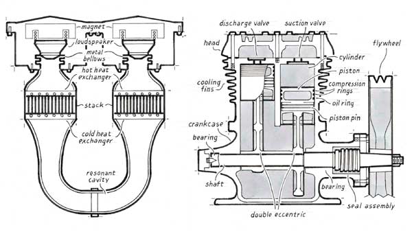
The U-tube contains two separate stacks, each with two water-filled heat exchangers, which resemble small car radiators, attached at the ends. Two of these heat exchangers exhaust waste heat, and two provide cooling. In this incarnation, chilled water from our "life sciences refrigerator" circulated through racks of radar electronics on the USS Deyo, a Navy destroyer. The maximum cooling capacity we achieved in our sea trials proved to be in excess of 400 watts, using just over 200 watts of acoustic power. At the lowest temperature of operation we could comfortably attain without risking the water freezing and blocking the pipes (about 4 degrees C), the refrigerator performed at 17 percent of the efficiency that could, in principle, be coaxed from a perfect refrigerator operating over the same temperature span—a fundamental limit imposed by the Second Law of Thermodynamics. The refrigerator itself reached 26 percent of the maximum, but inefficiencies of the heat exchangers reduced the useful cooling to the 17-percent value. That level is little better than half of what conventional chillers of similar size and cooling capacity can boast.
Although we could have improved the performance substantially with some modest changes, thermoacoustic refrigerators of this type will always have an intrinsic limit to their efficiency, which is imposed by the way heat flows between the gas and the stack. But recently, one of us (Backhaus) and his colleagues at Los Alamos National Laboratory demonstrated a technique that has enabled thermoacoustic engines to break this seemingly insurmountable barrier by, strangely enough, borrowing a technique that a Scottish minister patented in 1816—the very year Laplace first correctly calculated the speed of sound.
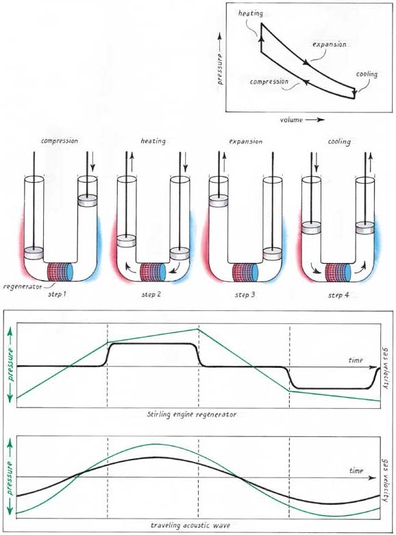
In his spare time, the Reverend Robert Stirling designed, built and demonstrated a rather remarkable type of hot-air engine, one that still bears his name. Unlike steam engines of the era, his invention contained no potentially explosive boiler. Stirling's engine depended on the expansion and displacement of air inside of a cylinder that was warmed by external combustion through a heat exchanger. Stirling also conceived the idea of a regenerator (a solid with many holes running through it, which he called the "economiser") to store thermal energy during part of the cycle and return it later. This component increased thermodynamic efficiency to impressive levels, but mechanical complexity was greater for Stirling's engine than for the high-pressure steam and internal-combustion varieties (which do not require two heat exchangers), restricting its widespread use.
The story of how one of the oldest ideas in the history of heat engines linked up with one of the newest is typical of the tortuous routes to discovery (or rediscovery) that many scientists experience. In this case, the journey began two decades ago, when Garrett had the pleasure of working with Gregory Swift, then a graduate student at the University of California, Berkeley. Swift eventually received his doctorate in physics and joined John Wheatley, who was just then preparing to move his low-temperature physics group to Los Alamos National Laboratory and focus his research efforts on the development of novel heat engines and refrigerators.
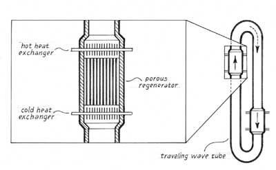
As a graduation present, Garrett gave Swift a copy of an intriguing article that Peter Ceperley, a physics professor at George Mason University, had published a few years earlier. It was entitled "A pistonless Stirling engine—The traveling wave heat engine." Ceperley cleverly recognized that the phasing between pressure and gas velocity within Stirling's regenerator was the same as the phasing in a traveling acoustic wave. He demonstrated that similarity by arranging a temperature gradient across a crude regenerator (a plug of fine steel wool) and sending a sound wave though it. Some thermal energy was converted to acoustic energy, though not enough to make up for the accompanying losses.
Swift brought Ceperley's article with him to Los Alamos, but he and his colleagues there decided that Ceperley's "engine" would never be able to amplify a sound wave and thereby produce useful power. The attenuation the sound suffered as it passed through the tiny pores in the regenerator would, it seemed, always overwhelm the modest gain that the temperature gradient created. So the Los Alamos physicists concentrated on using standing waves for acoustic engines and refrigerators, and, like several other research groups around the world, made considerable strides over the next decade and a half.
But in the past few years, the quest for improved efficiency led Swift, working with Backhaus, to reconsider Ceperley's approach. Looking again at the problem, we realized that the regenerator produces an amount of acoustic power that is proportional to the product of the oscillating pressure of the gas and the oscillating velocity of the gas. The power wasted in the regenerator is proportional to the square of the oscillating velocity. This loss is analogous to the power dissipated in an electrical resistor, which is proportional to the square of the current that flows through it.
Faced with such losses—say, from the resistance of the wires in a transmission line—electrical engineers long ago found an easy solution: Increase the voltage and diminish the current so that their product (which equals the power transferred) remains constant. So we reasoned that if the oscillatory pressure could be made very large and the flow velocity made very small, in a way that preserved their product, we could boost the efficiency of the regenerator without reducing the power it could produce.
These requirements led us back to acoustic standing waves used in more typical thermoacoustic engines as a way to obtain a high ratio of pressure to gas movement. Minimizing the flow velocity of the gas overcomes viscous losses inside the regenerator, whose tiny pores allow heat to move between gas and solid most efficiently. But using a regenerator instead of a normal stack changes the timing of heat transfer in a fundamental way: The oscillating gas has no time to shift position before the exchange of heat takes place. So it was not merely a matter of replacing a stack with a regenerator. The device that was needed had to reproduce some of the attributes of a standing wave (high pressure and small flow velocity) while also having some of the attributes of a traveling wave (pressure had to rise and fall in phase with velocity, not with displacement).
We were able to devise just such a hybrid by coupling a standing wave cavity (basically a long tube) with a dual-necked Helmholtz resonator. One neck is open to the flow of gas, and the other contains the regenerator and heat exchangers. The open passage acts much as a soda bottle does when one blows over its mouth. The mass of the air in the neck of the bottle and the springiness provided by the compressible gas trapped beneath it support oscillations—just as a solid mass and coiled spring do. Helmholtz developed this technique to amplify sounds in a narrow band of frequencies near the natural frequency of the resonator. The amount of amplification depends on how closely the frequency of the resonator matches the frequency of the sound that is incident on the neck.
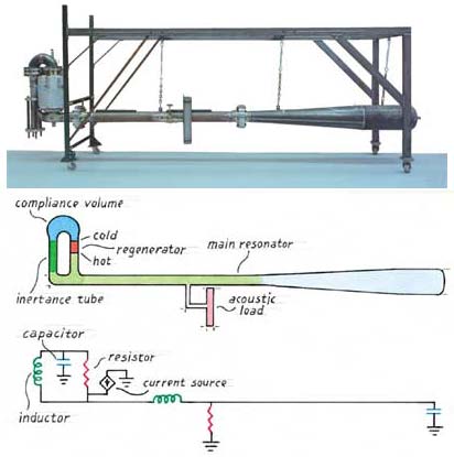
In our thermoacoustic Stirling engine, the natural frequency of the Helmholtz resonator is considerably higher than the frequency of operation. So the variation in pressure inside the Helmholtz resonator is only about 10 percent greater than inside the standing-wave resonator. Although modest, this difference is enough to drive some gas through the regenerator each time the pressure rises or falls—flow that is in phase with the changing pressure, just as in a traveling acoustic wave.
We thus neatly overcame the fundamental problem of Ceperley's traveling wave Stirling engine. But we were disappointed to discover that our engine performed rather inefficiently compared with our expectations. The problem turned out to be that the circular geometry of the two-necked Helmholtz resonator allowed gas to stream around the loop continuously, short circuiting the hot and cold ends of the regenerator and wasting large amounts of heat.
Once we realized what was happening, it was easy enough to correct the problem. One solution (which Ceperley had suggested years earlier for his circular design) would be to add a flexible membrane that passed acoustic waves yet blocked the continuous flow of gas. But prior experience with such membranes led us to believe that it would be hard to engineer something sufficiently robust to hold up over time. So instead we added a jet pump (asymmetric openings that allow flow to pass in one direction more easily than the other) to create a slight back-pressure in the loop, just enough to cancel the streaming. And we were pleased to find that the efficiency of the engine improved markedly. At best it ran at 42 percent of the maximum theoretical efficiency, which is about 40 percent better than earlier thermoacoustic devices had achieved and rivals what modern internal-combustion engines can offer.
Thermoacoustic engines and refrigerators were already being considered a few years ago for specialized applications, where their simplicity, lack of lubrication and sliding seals, and their use of environmentally harmless working fluids were adequate compensation for their lower efficiencies. This latest breakthrough, coupled with other developments in the design of high-power, single-frequency loudspeakers and reciprocating electric generators, suggests that thermoacoustics may soon emerge as an environmentally attractive way to power hybrid electric vehicles, capture solar energy, refrigerate food, air condition buildings, liquefy industrial gases and serve in other capacities that are yet to be imagined.
In 2099, the National Academy of Engineering probably will again convene an expert panel to select the outstanding technological achievements of the 21st century. We hope the machines that our unborn grandchildren see on that list will include thermoacoustic devices, which promise to improve everyone's standard of living while helping to protect the planet. We and a small band of interested physicists and engineers have been working hard over the past two decades to make acoustic engines and refrigerators part of that future. The latest achievements are certainly encouraging, but there is still much left to be done.
The authors gratefully acknowledge the generosity with which Greg Swift has shared his theoretical insights and technological innovations during the past 20 years with the world-wide community of thermoacousticians.
© Steven L. Garrett, Scott Backhaus
Click "American Scientist" to access home page

American Scientist Comments and Discussion
To discuss our articles or comment on them, please share them and tag American Scientist on social media platforms. Here are links to our profiles on Twitter, Facebook, and LinkedIn.
If we re-share your post, we will moderate comments/discussion following our comments policy.