Averting the Pall of Stall
By Lee S. Langston
Airflow disturbances in jet engines can cause rare but serious malfunctions.
Airflow disturbances in jet engines can cause rare but serious malfunctions.

As a Singapore Airlines flight was taking off from Melbourne Airport on August 25, 2004, the aircraft’s left engine surged. Within 70 seconds, the engine emitted 57 loud bangs, announcing in no uncertain terms that it was no longer fully functional. The pilot shut down the engine, dumped fuel, and completed a single-engine landing. An examination found that the liner of the casing surrounding the engine’s air compressor had eroded. Combined with the high levels of thrust produced during takeoff, this failure had caused a total breakdown of airflow through the engine, causing the surge condition.
A similar incident occurred in 2001 when a Delta Airlines aircraft bound for Japan safely aborted its takeoff at Portland International Airport. One of its engines had ingested a herring gull, precipitating a compressor surge that blew off the engine cowling and caused extensive damage to the landing gear.
Because of the high reliability of modern jet engines, most airline pilots can fly an entire career without experiencing an engine failure or having to shut down an engine for a minor problem. When instances of surge, and a related condition called stall, do occur, they usually are manageable and result only in mechanical issues, as these two events illustrate.
But that is not always the case, as exemplified by a fatal crash on November 13, 2018, when an experienced military instructor pilot was unable to safely eject from a supersonic training jet that underwent a compressor stall during a nighttime practice landing.
An aircraft’s propulsion is measured in pounds of thrust. To create thrust, an aircraft engine must compress air, combust the air with fuel, and expand the exhaust, which is accomplished in a gas turbine engine by a compressor, a combustion chamber, and a turbine, respectively. To efficiently compress a gas over the range of operating conditions that an engine experiences is not an easy task. Approximately 50–70 percent of a turbine’s power output is used to run its compressor. For comparison, a steam power plant uses only about 1 percent of its output to power the feedwater pumps that resupply water to the boiler.
Technische Universität Darmstadt/Bernhard Simon
The majority of gas turbine engines, both in power plants and in aircraft jet engines, use axial flow compressors to achieve the necessary compression. In these compressors, air flows through in an axial direction, parallel to the gas turbine’s axis of rotation. The compressor is composed of a number of stages, each comprising a ring of fixed-angle moving rotor blades, mounted on a rotating disc (or drum), and a downstream ring of case-mounted stationary rotor blades called stators. Rotor blades are like small wings that accelerate the movement of air, increasing its static and total pressure and its kinetic energy. Stators convert the air’s velocity into pressure to compress it; they further increase static pressure, decrease kinetic energy, reduce the swirling velocity the rotor blades can create, and align airflow to enter the next stage.
Compressor blades and stators then modulate the airflow to increase static pressure in the flow direction, which is a bit like pushing water up an inclined channel with many small, rapid brushstrokes. If the incline (akin to the compressor pressure ratio) is too steep, the water runs backward down the slope. Conversely, the airflow path in the axial direction has decreasing static pressure, and it’s as though water were being brushed down an inclined channel.
Early gas turbines had thermal efficiencies of approximately 18 percent. After eight decades of compressor design progress, modern gas turbines now have thermal efficiencies in the 35–45 percent range. A gas turbine’s thermal efficiency is directly increased by raising its overall pressure ratio. Years ago, an axial compressor with 15 stages might have had an overall pressure ratio of 4:1. Now, the 13-stage compressor in a General Electric GE90 gas turbine—currently the world’s largest and most powerful jet engine, which is used on the Boeing 777 for transoceanic flights—has an overall pressure ratio of 40:1. Other jet engine ratios can be as high as 60:1, representing a reduction of stages required and an almost fivefold increase in pressure ratio.
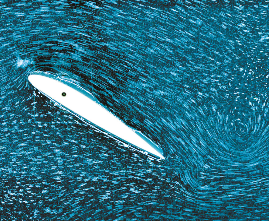
The flow around a compressor blade is controlled by its boundary layer, a very thin, almost immeasurable layer of air on the blade surface in which the effects of viscosity and friction are concentrated. Studies on boundary layers and other types of flow, often completed in water channels or wind tunnels, provide data that are used for aerodynamic research and to better understand the underlying physics of flow instabilities such as stall.
Engineers and engine manufacturers use such research facilities to visualize complicated aerodynamic shapes and their complex flow phenomena, which then inform aircraft design. Flow visualization experiments conducted in water channel facilities at the National Physical Laboratory in London, and the French aerospace lab ONERA, for example, advanced knowledge of air movement and control for the Concorde, the first supersonic commercial aircraft.
From this research, it has been discovered that within the boundary layer, the air velocity decreases from that of the air stream just outside it down to zero at a blade’s surface. Blades are shaped so that their leading edges have low pressure and their trailing edges have high pressure, and the air streamlines closely follow these suction and pressure surfaces. But boundary layers are very sensitive to the conditions brought about in compressors, where static pressure is increasing in the direction of flow. This pressure is the same as an increase in potential energy, which means a decrease in kinetic energy, and thus the air decelerates. The boundary layer is slowest at the blade’s surface, and so is most affected by this change. If it slows too much, it can separate from the surface, causing turbulence and airflow breakdown. Therefore, it’s necessary to ensure that such boundary layer separation does not occur, especially at the angles of the air inlets.
These constraints affect a compressor’s range of efficient operation. But the limits can be designed for by using compressor performance maps, historical data from previous failures, and velocity vector diagrams, which indicate the speed at which and direction from which airflow will enter an inlet. This modeling shows how inlet guide vanes and the first compressor stage should be built to ensure that the necessary air inlet flow angles for blades and stators are used to meet design operating conditions.
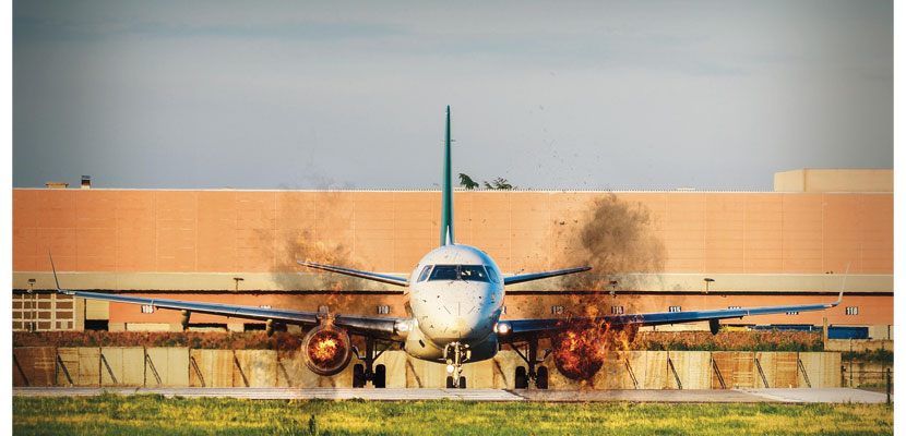
During surge, engine vibration increases, creating sudden banging sounds, and combustor-induced flames can shoot out.
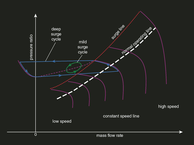
A typical compressor performance map is shown as a plot of pressure ratio, mass air flow rate, compressor rotor speed, and compressor component efficiency (see figure below). When a gas turbine company designs a new compressor, it will test it, varying flow rates and rotor speeds to measure pressure ratio and efficiency, and to determine the compressor surge line. This value marks the flow instability boundary, where the compressor can operate successfully to the right of the line and unsuccessfully to the left of the line. The key to successful compressor operation is the avoidance of stall, which results in compressor performance falling beyond the surge line or within a surge cycle zone.
Engine manufacturers then design engine control systems that are programmed to keep the compressor’s operating point away from the surge line. A computer-managed system called FADEC, or Full Authority Digital Electric Control, controls and monitors aircraft engine performance to correct issues and notify pilots of irregularities or mechanical problems. The specifics of these autonomous systems are often proprietary and vary by aircraft and engine model, but the underlying foundation remains consistent.
Compressors are designed to operate most efficiently at cruising speed. Because an aircraft will need to function within a wide range of speeds, additional features have been integrated into modern compressors to help control and regulate airflow and pressure. Inlet guide vanes direct air into the inlet, variable inlet guide vanes regulate air to maximize performance, variable pitch stators control angles of flow to rotors, compressor bleeds increase airflow through the compressor, casing treatments enhance stability, and tip clearance controls improve fuel efficiency. All are controlled through the FADEC to manipulate the air’s path, speed, and pressure to ensure that the compressor is operating efficiently at all speeds and to avoid stall conditions.
Modern design and fuel control systems usually keep a jet engine or an electrical power gas turbine away from operating conditions that bring about stall and surge, but it’s important to understand what can cause them. Stall is the partial breakdown of airflow through an engine. It’s a progressive condition that can lead to surge, which is the total breakdown of airflow through the engine. In extreme cases, surge can result in the reversal of airflow direction. In the words of Ivor Day—a prominent researcher on compressor surge, stall cell structure, and stall inception mechanisms—stall is a disturbance of compressor flow in the tangential direction, whereas surge is a disturbance in the axial direction.
Technische Universität Darmstadt/Bernhard Simon
When air inlet angles are increased, measured from the axial direction, separation of the blade boundary layers can occur and streamlines on the blade’s suction side do not follow the blade surface aft of the boundary layer separation point. Once this happens, the compressor blade is stalled.
Stall immediately increases a stage’s aerodynamic loss, decreases blade lift, and prevents the desired pressure increase. The increased air inlet angle generating the stall could be caused by an upstream flow disturbance or by sudden downstream back pressure leading to decreased air velocity, often the result of a blockage in the combustor or turbine. Other boundary layer separation causes include roughness of the blade surface and excessive tip leakage. In high-pressure stages, blades and stators get shorter, and blade tip clearance problems can also occur.
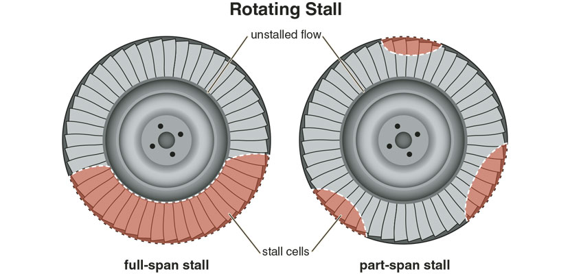
When one blade goes into stall, it can cause an upstream blockage that then diverts airflow approaching subsequent stages. This block can lead to an increase in the angle of airflow to adjacent blade passages in the opposite direction of the compressor’s rotation. If the angle increase is large enough, the blades will stall and a type of airflow stagnation called a stall cell will form. Average airflow through the compressor is steady during stalled operation, so the compressor will still operate, but less efficiently.
If the stall cell moves, it forms a rotating stall, which will rotate opposite to the compressor’s rotation but at a decreased speed. This disrupted flow causes increased stress on and vibration of the blades, which can lead to greatly shortened blade life. Rotating stall can morph into surge, which is the extreme case of compressor performance failure.
Barbara Aulicino
During surge, the flow rate will undergo rapid pulses, just milliseconds apart, that are sometimes violent enough to induce complete reversal of the airflow. Engine vibration increases, creating sudden banging or popping sounds. The reduced airflow in surge also increases exhaust gas temperatures, which can result in combustor-induced flames suddenly shooting out of the gas turbine exit and even the compressor inlet.
Depending on the situation, a pilot might shut down the engine and then attempt to restart it to see whether the stall condition resolves. The overwhelming majority of such occurrences end without incident, because crews are trained on simulators to handle the loss of an engine.
The onset of stall, and thus possible surge, can be traced to the behavior of the boundary layer on compressor blades and stators. Because these conditions are the result of the basic physics of boundary layers, no method of eliminating them has been found. However, because of their potentially serious outcomes, prevention of these conditions has been an active area of research and development in the worldwide gas turbine community.
Engineers first had to acquire a thorough understanding of the development of rotating stall and surge to determine how best to control and avoid it. Edward Greitzer, now at the Massachusetts Institute of Technology, is credited with defining the critical system parameters necessary for airflow to transition to surge, and for determining the requirements that made it possible for an engine to recover from rotating stall. These results enabled designers to reduce the occurrence of stall and surge, improve recoverability, and limit structural damage from surge.
Robert Mazzawy of Trebor Systems—who, in 1980, was one of the first to report on how surge induced loads on a structure—has noted that researchers have learned that subtle modal waves are precursors to the rotating stall that precipitates surge. Finding a way to detect these waves could allow the FADEC to prevent stall and therefore avoid surge, but these flow instabilities occur quite quickly, which makes detection more difficult.
One rotor revolution for an aircraft gas turbine typically takes about 5 milliseconds, and it takes several revolutions for rotating stall to develop. The nominal time period required for a variable stator or bleed to activate is around 200 milliseconds. The difficulty of having the FADEC sense a precursor and take the necessary action to prevent stall and surge becomes obvious when considering the disparity of these time intervals. Despite the difficulties of sensing modal wave precursors, current FADEC design provides other ways of using FADEC to successfully sense an impending stall or surge condition within a sufficient amount of time to either prevent its occurrence or limit repetitive surges.
Alexandre Rotenberg/Alamy Stock Photo
For example, such interventions are possible in twin-spool aircraft gas turbines—such as the Pratt & Whitney F119 on the F-22 Raptor and the Rolls-Royce BR715 on the Boeing 717—when the initial stall originates in the fan stream, usually because of foreign object damage, excessive clearance, or flow distortion from air separation at an inlet in the engine housing. A twin-spool turbine has low- and high-pressure stages operating at lower and higher revolutions per minute (RPM), respectively. In such a situation, stall in the compressor fan leads to a loss of flow capacity that causes the low-pressure stage’s RPM to increase above the normal power setting. Coupled with a normal high-pressure spool rotor RPM, this condition elevates the low-pressure stage’s operating line to its surge line, resulting in rotating stall and eventual surge. In this instance, the time required for the low- pressure spool to increase its RPM is long enough for the FADEC to intervene: It senses the unusual relationship between the RPMs of the low- and high-pressure spool and activates a bleed to prevent surge.
Another example is aircraft gas turbines operating in severe rain or hailstorms, when extra fuel is required to evaporate the water being taken in by the engine. The FADEC senses the abnormal amount of fuel flow for the power setting and takes action to prevent engine instability. Neither example is applicable to industrial gas turbines, but they illustrate that, if the FADEC can observe an unusual mode of operation, then it is possible to prevent stall and surge when given enough lead time.
In the early days of the gas turbine, lack of understanding of compressor stall cast a pall over jet engine development. Edward Taylor, the first director of MIT’s Gas Turbine Laboratory, wrote that early jet engine compressor designs foundered on a rock, and that rock was stall. Research on stall and surge has been in progress since World War II, and axial flow compressors have been continuously improved, now reaching component efficiencies in the 90-percent range. But no matter how advanced, compressors in aircraft jet engines must be carefully controlled in their operation to avoid the power-robbing effects of stall and the convulsive effects of complete flow reversal brought about by surge.
Click "American Scientist" to access home page

American Scientist Comments and Discussion
To discuss our articles or comment on them, please share them and tag American Scientist on social media platforms. Here are links to our profiles on Twitter, Facebook, and LinkedIn.
If we re-share your post, we will moderate comments/discussion following our comments policy.