In-tense Robots
By Stephen Piazza
Motorized sculptures may represent our best chance for exploring the surfaces of other worlds.
Motorized sculptures may represent our best chance for exploring the surfaces of other worlds.

DOI: 10.1511/2015.115.264
In the fall of 1948, a 21-year-old student named Kenneth Snelson invented an art form based on a new way of thinking about structural design. Snelson had been a painter, but decided to try his hand at sculpture after taking a summer course in three-dimensional design. He was experimenting with connecting rigid pieces of wood or metal with thin cables, and found that he could make the rigid pieces seem to float in midair if none of them directly contacted any of the others.
In contrast to a traditional structure where joints make the connections, the rigid pieces in Snelson’s works were held up only by tension in the nearly invisible cables. When he attended an art school the following summer, he brought with him one of his sculptures, two small wooden X-shapes connected by nylon cables, with one X appearing to float above the other. He showed it to one of his professors, the renowned architect and designer R. Buckminster Fuller, who was amazed at this column that lacked conventional joints. Fuller called Snelson’s structure a tensegrity, a name he created by combining the words “tensile integrity.”
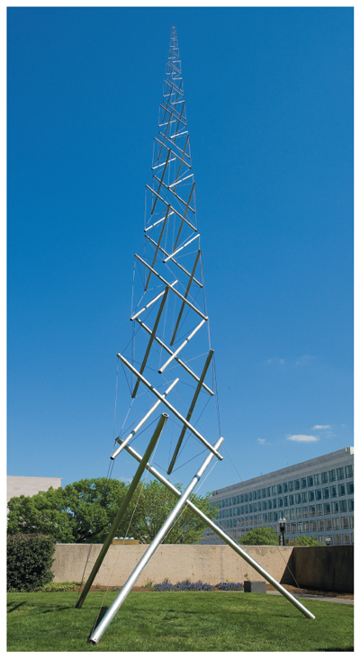
Snelson has gone on to create many tensegrity sculptures using straight steel tubes put under compression and steel cables pulled in tension (Snelson himself prefers the term “floating compression” to tensegrity). One resembling a tree (B-Tree) resides on the campus of the National Institutes of Health. Some are large and complex structures (Needle Tower, outside the Hirshhorn Museum and Sculpture Garden in Washington, DC, is 60 feet tall) that exhibit strength and stability that does not seem possible when one stops to think that they are essentially collections of struts held together by strings. An observer can “see” the loads, in a sense—cables can only be stretched, and they pull on the tubes in ways that could only compress the tubes along their length—yet it still seems mysterious how the structure maintains its integrity.
Snelson’s tensegrities are beautiful to behold, but they have also found application outside of visual art. Furniture designers have created interesting coffee tables and stools by placing platforms atop tensegrities. Because tensegrities are lightweight yet strong, architects began to incorporate them into their designs, and today there are sports arenas, houses, and bridges around the world that embody tensegrity principles, along with masts and antennas on spacecraft beyond this planet. Even the tent my family uses when we go camping is a tensegrity in a way, in that it has poles that are loaded in compression yet they are connected by only the tent fabric, which is in tension. Snelson has expressed skepticism regarding the optimality of tensegrities as structural elements, however; in 1990 he wrote, “the philosophy is akin to turning an antique coffee-grinder into the base for a lamp: it’s there, so why not find a way to put it to some use.”
To construct a tensegrity, one first decides on its topology: how many struts, how many cables, and how they are all connected. For a given topology, many different structures are possible depending on the lengths of the struts and cables, and some special properties of the structure will vary according to these choices. Although a tensegrity is made in part of rigid members, the structure as a whole is compliant. Applying a force to a tensegrity structure will cause it to give way slightly and then it will snap back to its original shape when the force is removed, as would a spring.
In the early 2000s Robert Skelton and his colleagues at the University of California, San Diego were among the first to see tensegrity structures as controllable, in which element lengths or forces could be set in order to achieve a desired shape for the structure, or a desired degree of compliance. Taking this concept a step further, they wondered, what if this control of length or force could be made to change over time? With a defined pattern of controlled changes, a tensegrity structure could move—the basis for a tensegrity robot.
A tensegrity robot whose mechanical properties could be dynamically tuned could be made taller or shorter depending on how far it needed to reach, or its compliance could be varied according to the type of vibration it was expected to encounter in its working environment. Skelton’s team built such tensegrity robots, including a simple X-shaped crawler that inched along when two different sets of cables were tensed alternately.
Mechanical engineers Chandana Paul, Francisco Valero-Cuevas, and Hod Lipson, working at Cornell University at the time, developed computer models to create control schemes for the locomotion of more complex tensegrity robots. In a 2006 paper in the IEEE Transactions on Robotics, they simulated a robot with four rigid cylindrical struts. Cables connecting the ends of the struts were modeled as elastic cords whose forces depended on their lengths. The robot model was driven in different ways by simulated motors that changed either the lengths of the cables or the lengths of the struts.
The Cornell group faced a challenge when it came to figuring out a way to make their simulated robot go. Controlling a mobile robot that has wheels is relatively straightforward. If you want the robot to travel farther, you use the motor to make the wheels turn; if the robot begins to veer off course, you adjust the steering to make a correction. Controlling a tensegrity robot is a much less intuitive proposition. Changing the length of any given strut or cable might not make the robot go anywhere. If changing a length introduces too much slack into the system, the robot might collapse in a jumble of struts and cables.
To solve this problem, the authors initially assumed that the best solution would involve the robot adopting a repeating gait in which strut or cable lengths would change in a periodic fashion. They then assumed a default form for these periodic length changes and used a genetic algorithm to find parameters for each cable or strut motor that produced the most efficient locomotion. In this approach, many different sets of parameters are tested to see how far each makes the robot move in ten seconds. Some will not make the robot move at all (these are discarded), but some parameter choices will produce motion in the desired direction. The best of these are then used to produce (through mixing and randomly mutating) a new collection of motor parameter sets with the potential to make the robot travel even farther, and the entire process is then repeated over hundreds of generations.
The evolution simulated by the genetic algorithm produced different gaits each time it was applied. The authors reported that one gait involved the robot “dragging two of its struts along, using the third as a pick axe” to pull itself forward. Other gaits were more dynamic, bounding movements with bouncing phases in which the entire robot would leave the ground briefly.
Paul, Valero-Cuevas, and Lipson tested whether locomotion was still possible with a broken tensegrity robot and, amazingly, it was. The robot was still able to limp along, although it traveled less distance and in paths that became more curved when more of its motors were broken. To test whether a real robot could move like its simulated counterparts, the team constructed a tensegrity robot with 40-centimeter-long aluminum struts, with its motors driven using a timing pattern derived from the simulation. It was found to cruise along at 60 centimeters per minute—not particularly fast, but that it moved at all validated the feasibility of tensegrity robot locomotion.
The 2006 study demonstrated some important capabilities of tensegrity robots not noted previously. It showed not only that tensegrity robots could move, but that they are especially well suited to an application that requires a mobile robot that can maintain its locomotion even if it breaks, because the nearest repair technician is many miles away.
In December 1999, NASA’s Mars Polar Lander arrived at its destination and was poised to begin its survey of the climate and terrain near the south pole of Mars. The plan was for the massive lander (290 kilograms) to enter the Martian atmosphere, have its fall slowed by a parachute, then begin a powered descent that would bring it to within a few meters of the planet surface.
At 40 meters altitude, however, a malfunction caused the lander’s sensors to indicate that it had already reached the ground, and the lander’s engines automatically shut off. According to the Jet Propulsion Laboratory report on the loss of the lander, it struck the surface traveling at 22 meters per second, about 10 times faster than the impact velocity for which the lander was designed. The lander was never heard from again, bringing its 11-month mission to an abrupt and disappointing end.
Today, NASA engineers are developing a new generation of tensegrity robot landers that they hope will be immune to rough landings, and thus eliminate the need to avoid them. A team co-led by Vytas SunSpiral and Adrian Agogino from the Intelligent Systems Division at NASA Ames Research Center and their colleague David Atkinson from the University of Idaho has created Super Ball Bot, a six-strut mobile tensegrity robot. Super Ball Bot is driven by motorized winches in the struts that control the lengths of its cables, and will carry a payload of sensors necessary for exploring the surface of a planet or a moon.
One possible future mission for this kind of robot is exploring the surface of Titan, the largest moon of Saturn, whose rough terrain features rolling sand dunes, craters, and mountain ranges that would require a tough lander design. Like its Cornell predecessor, Super Ball Bot has enough built-in redundancy that a broken cable will not deter it from completing its mission, but robustness is not its only desirable quality.
A tensegrity robot would likely be cheap enough and small enough (when folded up) that several could be deployed on a single mission and explore the surface of a planet or moon in parallel. A tensegrity robot likely would be lightweight, perhaps only about 40–75 kilograms depending on which sensors are included. It would also have a high degree of built-in compliance which, along with its low mass, lead the NASA team to believe that the impact forces that were fatal to the Mars Polar Lander would be much smaller for Super Ball Bot.
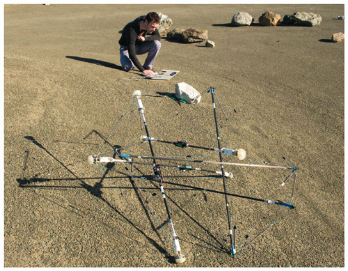
Tensegrity Kit robot V3 completing a roll test on the NASA Ames roverscape on July 17, 2015. First test of kit robot on loose terrain. Link to the video .
Simulations of landings predict that Super Ball Bot would be rugged. A tensegrity robot striking the surface at 15 meters per second would experience impact forces that are 86 percent smaller than those expected for a conventional lander that is traveling at the same speed, perhaps because of a failure in its landing systems. Rather than striking the ground with a violent thud, Super Ball Bot would have a more cushioned landing and bounce into the air (well, it’s almost all nitrogen on Titan) several times before coming to rest.
Rather than striking the ground with a violent thud, Super Ball Bot would have a more cushioned landing and bounce into the air several times before coming to rest.
SunSpiral told me about some other potential advantages of a tensegrity robot lander; one of these is energy efficiency. “If you get it right, a tensegrity robot can be very efficient in how it moves and changes shape,” he said. “With the appropriate sensing on tension, you can have some motors releasing cables as other ones are tensing, and this can minimize energy expenditure during shape change. It’s been shown theoretically that for a redundant tensegrity structure that has more than the minimal number of connections, there are many shape changes that can happen with essentially no work.”
Tensegrity Kit robot V3 completing a roll test on the NASA Ames roverscape on July 17, 2015. This was the first test of any tensegrity robot on an uphill grade. Link to the video.
Watching the Super Ball Bot prototype move is an oddly thrilling experience (video is available at https://www.nasa.gov/content/nasa-360-talks-super-ball-bot/). At first it doesn’t seem to be moving much at all; then suddenly it jerks forward in a spasm of motion, followed by another slow-motion period, and another lunge forward. SunSpiral says that often what is happening when the robot suddenly lurches is that the Super Ball Bot is altering its base of support until the robot must fall forward under the influence of gravity.
The physics is similar to what happens when a lumberjack fells a tree. Instead of the tree being pushed, its base is slowly removed until gravity takes over. Human walking can also be thought of as a series of falls and recoveries but differs from the robot because the base of support (the foot of the leading leg) does not change. When we walk, it is the body’s center of mass moving forward past the front foot that triggers the fall forward.
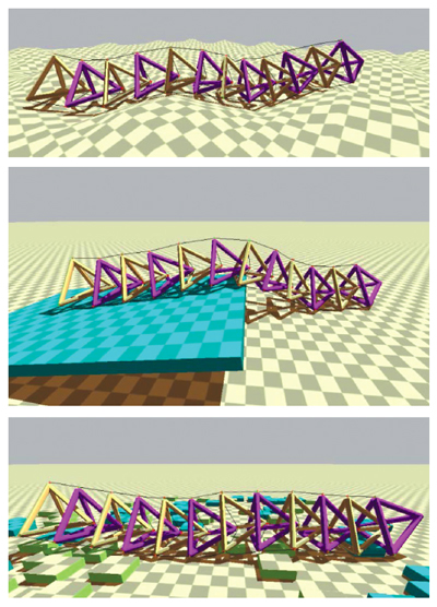
Knowing that Super Ball Bot has a goal of locomotion in mind makes its motion seem somewhat eerie to me, because living things that move over land in a goal-directed way do not look much like this ball-shaped tensegrity robot. It reminds me instead of a smart tumbleweed that requires no wind to drive it. Other tensegrity robots developed by the NASA Ames group, however, look more like living things. Their Tetraspine robot is a series of nested tetrahedrons, with cables connecting each individual tetrahedron to its neighbor in front and in back. If it looks a little like a human spine lying on the ground, that is no accident; the design was inspired by the “biotensegrity” models of the spine created by the artist Tom Flemons and orthopedic surgeon Stephen Levin.
To control the Tetraspine, a biologically inspired strategy (the same scheme as Super Ball Bot’s) is used in which a network of what are called central pattern generators drive the motion. Each one is an oscillator that is set to run out of phase with the others to produce a wave of motion that propagates down Tetraspine’s body, producing an undulating crawl. The parameters that define each oscillator are found by searching for those parameters that produce the greatest travel in a set amount of time using machine-learning approaches similar to the genetic algorithm previously used by the Cornell group.
When I asked SunSpiral to name the most impressive feature of tensegrity robots, he cited one that they share with living things: “Everything in biology is compliant. There are very few very rigid structures and yet that is not how we have been building our robots to date. The awesome thing about tensegrity structures and their tensile networks is that when you apply a load to them, that load diffuses through the structure and the whole structure adapts to its most efficient shape to manage that load.”
The compliance built into tensegrity robots may also improve the performance of more conventional biologically inspired robots, such as those that walk on legs to climb over obstacles, according to Brian Mirletz, a graduate student in mechanical engineering at Case Western Reserve University who worked with the NASA team on the Tetraspine. “We’re starting to examine how the spine might improve the performance of a quadruped robot, because right now all of the [quadruped’s] legs transmit forces to a body that is a rigid box in most cases,” he said. This setup is problematic because large forces applied to a rigid body tend to produce high-stress concentrations that may lead to failure. “A series of hinges that you would find in a snake robot doesn’t necessarily solve that problem,” said Mirletz, “but a tensegrity robot might.”
Super Ball Bot can currently travel at about 1 meter per second in simulations, only about the speed of a slow human stroll. But the unique properties of tensegrity robots make it very likely that they will soon be traveling quite far.
Click "American Scientist" to access home page

American Scientist Comments and Discussion
To discuss our articles or comment on them, please share them and tag American Scientist on social media platforms. Here are links to our profiles on Twitter, Facebook, and LinkedIn.
If we re-share your post, we will moderate comments/discussion following our comments policy.