The Right Mount
By Lee S. Langston
How and where engines are affixed to aircraft wings can be a complex challenge.
How and where engines are affixed to aircraft wings can be a complex challenge.

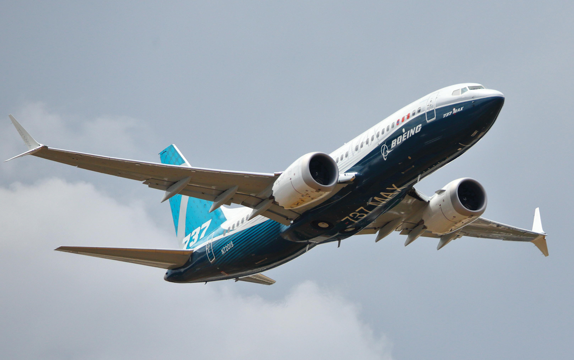
Whenever I get a window seat on a large airplane, the view of a mighty jet engine mounted under the wing in flight is an awe-inspiring sight for me—especially during rough weather that can noticeably deflect the wing. I marvel at the engineering required for the engine mounts to keep the engine safely attached, while simultaneously transmitting thrust for flight, carrying engine weight, and supporting the aerodynamic forces buffeting the engine’s housing, called a nacelle.
The first commercial jetliner, the 1947 de Havilland DH.106 Comet, had its engines embedded into its wings, at the base near the fuselage of the airplane. But a year before, Boeing had developed a bomber (its Model 450, which became known as the B-47 Stratojet) that had jet engine pods hung on thin struts called pylons, well below and ahead of the wing’s leading edge. Since then, airline designers have largely followed the Boeing stratagem of underwing engine mounting.
Uwe Deffner / Alamy Stock Photo
Engine mounts have a complex job. The thrust forces that move the aircraft, generated by gas flow changes in a jet engine, are transmitted by pressure and friction forces onto components and struts attached to the engine case. Case engine mounts then transmit the thrust forces (as high as 100,000 pounds or 445 kilonewtons of force on the largest engines) to the wing pylon mounts, to pull the plane forward. The mounts must also support the engine’s weight (as much as 20,000 pounds or about 9,000 kilograms) and carry the load of aerodynamic forces on the nacelle during flight. Because engine casings experience wide variations in temperatures and loads, some engine mounts incorporate an ability to move, to allow the casings to expand and contract freely in both axial and radial directions. All of these factors add up to a wide range of variables that must be within strict parameters, or the results can be catastrophic.
Engine mounts were indirectly involved in two fatal crashes of the Boeing 737 MAX, an aircraft that was introduced after its certification by the Federal Aviation Administration in March 2017. One crash occurred on the edge of Indonesia’s Jakarta Bay after takeoff of Lion Air Flight 610, on October 29, 2018, killing all 189 people on board. The second crash took place on March 10, 2019, again on takeoff, from Addis Ababa, of Ethiopian Airlines Flight 302, killing all 157 people on board.
These two crashes, which claimed a total of 346 lives, resulted in the worldwide grounding of the 387 existing 737 MAX aircraft by March 18, 2019. Subsequently, after better documentation and training for pilots and costly work to fix contributing operational and design problems, regulatory bodies allowed MAX commercial flights to resume in late 2020 and early 2021. As of January 2023, Boeing was required to appear in court to face the families of victims of those crashes, who are challenging the settlement that the American government reached with the company.
In addition to the tragic loss of human life, this dire series of events has presented a major financial hit to Boeing, as well as inflicting reputational harm on the company, revered for its long and successful aviation history. Estimates vary, but the accidents and grounding costs to Boeing may be $20 billion or more, with indirect costs as high as $60 billion from canceled MAX orders.
In the continuous pursuit of airline fuel economy, engine fan sizes are ever growing, and safely mounting engines under a wing will remain a daunting task.
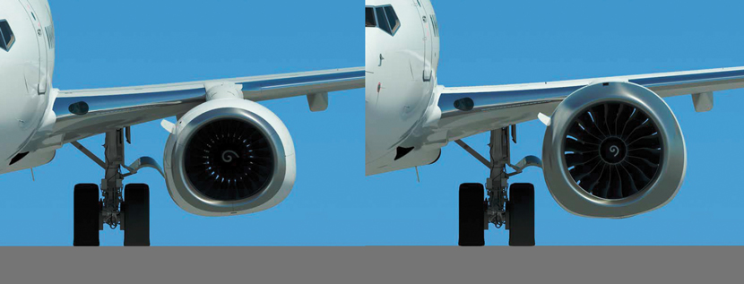
The original Boeing 737, first flown in 1967, is an almost 60-year-old design. After resolving some initial design hiccups, it has proven to be the most popular twin-engine airliner, with the 10,000th 737 rolling off Boeing’s Renton, Washington, production line in 2018, powered by CFM International’s CFM56 engines. The CFM56 turbofan engine has a 60-inch (152-centimeter) fan diameter. Power and fuel efficiency in turbofan engines are determined by what is called the bypass ratio, the mass of air bypassed around the engine for every unit of mass of air through the engine (see “Gears Drive the World,” Technologue, March–April 2022). The CFM56 has a bypass ratio of 5:1. The nacelle inlet shape on the 737 is flattened on the bottom, a design consideration that allows it to use a larger engine while maintaining a required taxiing ground clearance of 17 inches (43 centimeters). The airline industry has given the flattened shape of this engine opening the nickname of “hamster mouth” (see figure below).
In the quest for greater fuel economy, the 737 MAX had the CFM56 engine replaced with CFM International’s new LEAP turbofan. LEAP (for Leading Edge Aviation Propulsion) has a bypass ratio of 9:1 (and thus higher fuel economy) and a 69.4-inch (176.3-centimeter) fan diameter, providing more power.
Leeham News
With the increased fan size, the LEAP engine nacelle had to be mounted slightly higher and further forward on the wing from the previous CFM56 engines, to give necessary ground clearance. But an unintended consequence of this new location and larger nacelle is that during flight, it causes air vortex flow off the nacelle body, which produces unwanted lift at high flight angles, especially during aircraft climb at takeoff. Because the LEAP nacelle is in front of the plane’s center of gravity, this unintended nacelle lift causes a slight effect in which the nose of the aircraft pitches up. If sustained, this pitch-up brings the aircraft closer to stall and causes a devastating loss of aircraft lift. (See “Averting the Pall of Stall,” Technologue, January–February 2020.)
Having some background as a gas turbine aerodynamicist, I would have expected Boeing to eliminate the unwanted nacelle lift directly. That process might have entailed changes to the surface of the nacelle to break up the vortex airflow, and extensive wind-tunnel testing.
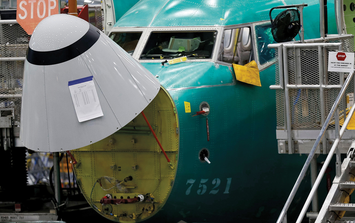
But instead of aerodynamic fixes for this unwanted LEAP nacelle lift, Boeing engineers created an automated anti-stall system, called MCAS (for Maneuvering Characteristics Automation System). This software code expands how the 737 MAX tail-mounted horizontal stabilizer is automatically adjusted to counter the unwanted nacelle lift. This flight control software depends on a sensed flight angle (called the angle of attack) from a fuselage-mounted sensor (see figure below). Malfunction of the sensor combined with MCAS system flaws are what led to the two 737 MAX fatal crashes.
REUTERS / Alamy Stock Photo
The 737 MAX MCAS controls fix that was chosen by Boeing may have been more expedient, but it cost many lives and could cost the company more in the long term.
Although many of the engineering details behind the LEAP engine mounting troubles are still proprietary, other cases can provide insight.
I can give a more detailed, first-person account of an earlier episode of engine mounting troubles, this time involving the iconic Boeing 747. With its maiden flight on February 9, 1969, Boeing’s four-engine 747 was the first commercial jumbo jet. It is the most successful wide-body passenger aircraft yet developed, with more than 1,500 produced to date; its more than a half-century production run at Everett, Washington, ended in 2022.
As a young engineer in the 1960s at Connecticut’s engine company, Pratt & Whitney Aircraft (now Raytheon Technologies’ Pratt & Whitney), I had some personal involvement with solving engine mounting troubles with the 747’s inaugural engine, the PWA JT9D.
Less than six months after its maiden flight, it was determined that the JT9D engine case was excessively bending and ovalizing—distorting into a non-circular shape—under thrust loading that could be as high as 43,500 pounds of force (194 kilonewtons) during takeoff. The ovalizing distortion resulted in turbine and compressor blades rubbing against the interior of the engine case and necessitated power-robbing increases in blade tip clearance gaps. The result was a serious reduction in thrust, and increased fuel consumption, as much as 7 percent above what the manufacturer had guaranteed.
Both Boeing and Pratt & Whitney were essentially betting their net worth on the 747. At one time, there were 15 four-engine 747 jets sitting engineless on Boeing’s Everett tarmac, representing $360 million—or more than $2 billion in 2023 dollars—of stranded assets. Getting those planes into the air was an engineering and commercial imperative. As Time magazine reported in September 1969:
On the apron outside Boeing’s plant in Everett, Wash., 15 enormous 747 jets stand high and silent, harbingers of a new era in aviation. They are painted in the colors of several international airlines: TWA, Pan Am, Lufthansa, Air France. For the moment, however, the planes are the world’s largest gliders—because they have no engines. Pan Am had been scheduled to get the first three commercial giants, each with a capacity of 362 passengers, in late November. Last week embarrassed Boeing officials said that performance difficulties in the Pratt & Whitney JT9D engines would delay that delivery as much as eight weeks.
When a major problem like this occurs, an engine company will try multiple paths to find the cause—and the cure. In my own case, I worked with an engineering team on an investigation of possible thermal effects that might be causing the engine case distortion. This multiple-path approach ended when it became clear that the distortion was a structural problem, caused by the position of the main thrust mount on the turbine case.
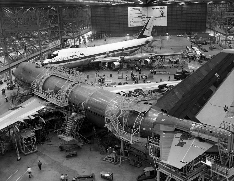
Photo 12/Alamy Stock Photo
Pratt & Whitney structural engineers then conducted extensive static JT9D case deflection tests and analysis. They found that if two—rather than one—thrust mounting points were circumferentially located 90 degrees apart at any one axial position on the engine case, the resulting ovalization of each would cancel the other, greatly reducing overall case distortion. This two-point distortion canceling method was very effective, so much so that the results were extended to show that the two mounting points could be separated by as much as 120 degrees and still yield an acceptable amount of case distortion reduction.
The Pratt & Whitney team then devised and designed a Y-shaped titanium tubular thrust frame with arms that were fastened to the case around the compressor at two fixed mounts, about 120 degrees apart. The leg of the thrust frame then attached to the rear turbine case mount through an axially sliding joint, to accommodate engine axial length changes, and that mount was rigidly affixed to the pylon.
Subsequent engine tests showed that the new thrust frame substantially reduced ovalization. Maximum thrust could be achieved with little case distortion, and engine performance now met guaranteed fuel consumption specifications. The new thrust frame (which became known as the “yoke” at Pratt & Whitney) added about 163 pounds (74 kilograms) of weight to the 8,600-pound (3,900-kilogram) JT9D, and required a relocation of several external engine components. But as an add-on, the frame didn’t necessitate an additional FAA certification of the engine, and it solved the ovalization problem that was threatening the financial future of both Boeing and Pratt & Whitney Aircraft.
The mounting of jet engines continues to challenge airframe and turbofan jet engineers. For proprietary reasons, not much is published in the open literature, but patent listings give an idea of the ongoing technical activity in jet engine mounting.
In the constant pursuit of airline fuel economy, engine bypass ratios are increasing (12:1 on new geared fan engines), with fan sizes ever growing (178 inches [452 centimeters] on the new General Electric GE9X turbofan engine). Safely mounting engines under a wing will remain a daunting task.
Click "American Scientist" to access home page

American Scientist Comments and Discussion
To discuss our articles or comment on them, please share them and tag American Scientist on social media platforms. Here are links to our profiles on Twitter, Facebook, and LinkedIn.
If we re-share your post, we will moderate comments/discussion following our comments policy.