Gears Drive the World
By Lee S. Langston
This ancient technology continues to turn up in the most modern of places.
This ancient technology continues to turn up in the most modern of places.

The gear is one of the oldest known machine parts, born from the humble mechanical engineering foundation of the lever and the wheel. Gears have evolved into many specialized forms, such as oval gears used in mechanical flowmeters, screwlike worm gears used in the tuning keys of some stringed instruments, and flexible, compact strain wave gears used in robotics.
Thousands of years after their invention, gears are still ubiquitous, used in flow-control devices in nuclear power plants, steering and power transmission systems in automobiles, coffee grinders in espresso machines—even in the sunshield structure of the recently launched James Webb Space Telescope. Remarkably, engineers are still finding new ways to refine and apply this ancient technology. One of the most noted, and paradigm-shifting, recent advances in commercial aviation is being propelled by the modest gear.
Gears use the principle of the lever to alter speed and torque carried by rotating shafts in machines and mechanisms within machinery. Broadly, a gear is circular, with cut or inserted teeth on its circumference. The teeth mesh with the teeth of one or more other gears to transmit power and control rotational speed. Gear teeth can take many forms: Modern spur gears have straight teeth, whereas helical gears have teeth oriented at an angle to the gear shaft.
The most common type of gear tooth profile is formed from the involutes of a circle. Similar to the Archimedean spiral, the involute of a circle is a curve dependent upon the shape of the circle. Involute gear teeth allow meshing to occur between teeth by a pure rolling contact—rather than a sliding (friction and heat) motion other gear profiles use—and they maintain a constant ratio between gears. By changing the size of the gear, the resulting speed and torque can be increased or reduced as needed. Using these artful and unassuming mechanisms, humans can take power from a source, modify it to fit the intended purpose, and deliver it to the desired application.

© 2020 Tony Freeth
The technology of gears has been traced as far back as 3000 BCE, to Chinese travelers crossing the Gobi Desert using two-wheeled chariots. One type of chariot had an advanced guidance system: A wheel-mounted differential gear train mechanism, composed of wooden pin teeth, would operate an outstretched arm that, once aimed southward, would maintain that constant direction despite the turns and movement of the chariot. Some of the earliest waterwheels and windmills transferred power through wooden peg tooth gears, and early tower clocks used crown gears in iron timekeeping mechanisms.
One of the most famous of ancient gear assemblies is the Antikythera mechanism, discovered in 1901 among the wreckage of an ancient Roman ship. Possibly constructed in Rhodes in 150–100 BCE, the Antikythera mechanism is an astronomical analog calculator, or orrery, driven by a clockwork mechanism. It was likely used to predict celestial positions of the Sun and Moon, the time of solar eclipses, and the dates of Olympic and Panhellenic games. It was operated using a small hand crank (which has since been lost) linked to a crown gear to rotate the interlocked gears and what are called epicyclic gear trains within. Also called planetary gears, epicyclic gears have a central “sun” gear that meshes with one or more surrounding intermediate gears; these are held in a carrier and enclosed in a ring gear. Although heavily corroded by its 2,000 years in the sea after being lost in a shipwreck off the Greek island of Antikythera, the mechanism has been determined to have had at least 30 metal gears with triangular teeth.
Gears saw consistent use in select applications for hundreds of years, but they didn’t enter widespread adoption until advances in mathematics and production developed. The understanding of more complex mathematical concepts, such as involute curves, progressed in the late 1600s, allowing gears to be refined for use in more complex tasks. Indeed, the thesis for the first engineering doctorate in the United States, awarded to Josiah Willard Gibbs in 1863, was titled “On the Form of the Teeth of Wheels in Spur Gearings.” Gibbs’s work dealt with “the necessary relations between the surfaces of the teeth of wheels, in order that they satisfy the various conditions of practical utility.” Gibbs went on to become a professor at Yale University and a renowned thermodynamics engineer and scientist.
In the early 1800s, the Industrial Revolution brought gears into mass production using form cutters and hobbing, a machining process that uses a specialized milling device and a cutting tool called a hob to cut gear teeth. Patents for hobbing processes were filed by English inventor Joseph Whitworth in 1835 for spiral gears, and by Robert Hermann Pfauter in 1897 for both spur and helical gears. These hobbing processes allowed more complex gear teeth, such as involute gear teeth, to be produced accurately and consistently, and at a much faster and cheaper rate than other gear-forming processes.
Once gears were more readily available, they began to appear in existing machines. Integrated to improve a machine’s effectiveness, accuracy, speed, or consistency, gears often advanced more than one of those factors and by significant margins. Gears were also linked together in assemblies called gear trains, which provided significant improvements in how power could be transferred and manipulated.
As mentioned, changing the size of the gear influences the resulting speed and torque, which is determined using what’s called the gear ratio, a measurement of the rotational speeds of two interlocking gears. A driver, or input, gear is attached to a power source and transmits that power to a driven, or output, gear. A 3:1 gear ratio means the driver gear rotates three times and the driven gear rotates once. Where two gear teeth connect is called a pitch point, and the line of these connected pitch points is called the pitch circle.
© 2022 Pratt & Whitney. Reproduced with permission.
Because the radius of a gear’s pitch circle is proportional to the number of teeth on the gear, a simple way to determine gear ratio is to divide the number of teeth on the driven gear by the number of teeth on the driver gear. If the driver gear is smaller than the driven gear, input torque is amplified and speed is decreased; if the driver gear is larger than the driven gear, input torque is reduced and speed is increased. Consider a 3:1 gear ratio again. This ratio means that the driven, or output, gear has three times the torque and runs at one-third the speed of the input gear. When output speed is reduced, this is called gear reduction.
The understanding of more complex mathematical concepts, such as involute curves, progressed in the late 1600s, allowing gears to be refined for use in more complex tasks.
In the United States, the most well-known historical example of the paradigm shifts that gears can bring about is likely the Whitney cotton gin. In 1794, Eli Whitney patented an improved cotton gin that used gears in many of its models to transmit power to the separation mechanism. His gin (a name probably derived from “engine”) was a breakthrough machine that successfully separated cottonseed from raw cotton fibers. It made growing cotton very profitable and set the plantation-based economy of the American South on a collision course with the industrial North. So it could be said that gears helped set in motion the events leading to the American Civil War.
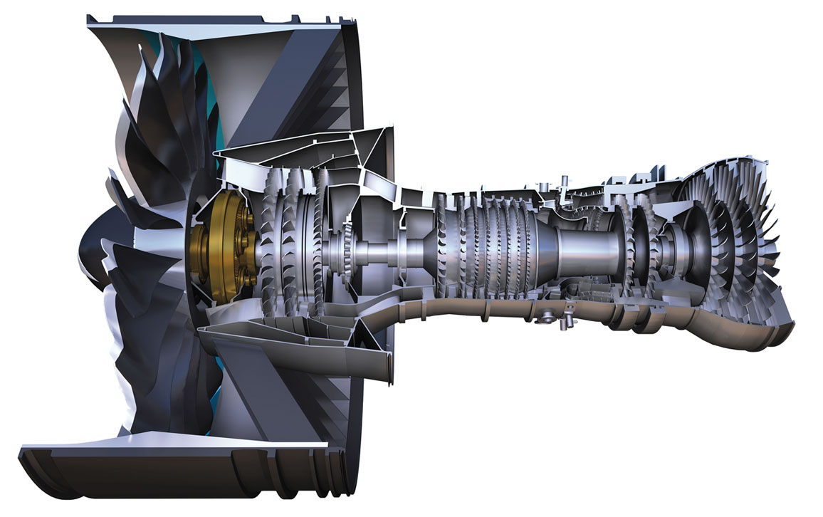
In the current era, commercial aviation is primed to be the next field to experience a fundamental shift thanks to the gear. In January 2016, aerospace company Pratt & Whitney provided its first geared turbofan jet engine—the PW1100G, a machine with 30,000 pounds (136 kilonewtons) of thrust—for aircraft. This engine now powers more than 1,000 aircraft across 51 airlines, and is bringing radical change to commercial jet engine flight. Its design integrates a gear train, specifically an epicyclic one, into the jet engine to maximize the efficiency of the engine components, pushing them beyond the limits of nongeared engines.
Exploring these improvements requires touching on the basics of jet engine flight. The first commercial jetliners were powered by turbojets—jet engines in which all thrust is provided by gases that go through the engine from inlet to exhaust nozzle, exiting in a single high-velocity jet. The resulting momentum increase provides the thrust force necessary for flight, but kinetic energy is wasted in the exiting jet, because the energy available from the gas exiting at high speed from the engine isn’t used.
A more efficient design is the turbofan jet engine, so named for a ducted fan mounted in the front. Air drawn into the fan is divided, with some flowing through the fan into the jet engine itself and the remainder bypassing the engine. The lower-velocity bypass air and the higher-velocity engine air combine downstream to produce thrust with a larger mass flow at an average velocity lower than the high-velocity jet exit flow. The addition of lower-velocity bypass air provides the same thrust but with less fuel consumption.
© 2022 Pratt & Whitney. Reproduced with permission.
With a large frontal area, the commercial aircraft turbofan is designed to produce peak thrust at takeoff, with most of the thrust produced by air drawn in by the fan and bypassing the jet engine core itself. Having some air bypass the engine core allows a wider range of aircraft performance: High-bypass engines provide aircraft with high propulsive efficiency, reduced noise, and improved fuel efficiency. Bypass ratios—the mass of fan air bypassed for every unit mass of air through the engine—currently can be as high as 8.4:1, as in General Electric’s GE90 engine that is used on Boeing 777s and produces 100,000 pounds (445 kilonewtons) of thrust.
Although impressive, this bypass ratio marks the height of efficiency for nongeared engines. To achieve better performance and fuel conservation, a substantial change in engine design is called for, because the fan and the engine have diverging needs. On one hand, the compressor and turbine assembly, known as a spool, within the engine are most efficient at high rotational speeds. But the much-larger-diameter fan operates most efficiently and creates less noise at lower rotations per minute.
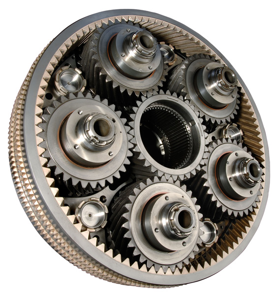
The solution Pratt & Whitney engineers came up with involves separate gear-connected shafts for the fan and the compressor/turbine spool, and an epicyclic gear train mounted on the fan’s hub. Introducing a gearbox into the turbofan design allows each of these two specific engine components— the fan and the turbine—to run closer to its optimal speed.
A gearbox is a gear train contained in a housing. The designers went with an epicyclic gear train because it provides significant gear reduction in an efficient and compact component. (In an epicyclic gear train, the gear ratio is determined by the sun, or driver, gear and the ring, or driven, gear.) Currently, Pratt & Whitney’s first-generation geared turbofan engines use a gear reduction of 3:1, with a resulting bypass ratio of 12:1. The real benefit turns up in the engine’s efficiency: The resulting fuel consumption is as much as 16 to 20 percent lower than current conventional fan engines. And the noise reduction is also substantial, with the characteristic turbofan whine being replaced by a lower-frequency “whoosh.”
Introducing a gearbox into the turbofan jet engine design allows each of the two specific engine components—the fan and the turbine—to run closer to its optimal speed.
Even so, it is critical that the geared turbofan gearbox be very efficient in transmitting the high levels of power from the compressor/turbine spool to the fan. In more recent models of geared turbofan engines that followed the one from Pratt & Whitney, such as those from Mitsubishi and Airbus, the transmitted power is as high as 18,000 to 30,000 horsepower. All gearboxes have friction, which generates heat. A lubricant helps control that friction, reduce wear on the gear teeth, and dissipate heat. But even small inefficiencies such as gear tooth mismatch and bearing misalignment would generate enough heat to “cook” gearbox lubricating oil. Testing has shown that geared turbofan gearboxes must be at least 99.3 percent efficient to avoid that problem.
One drawback to gearboxes is that they add weight, but that can be offset by eliminating components in the engine core. A conventional gas turbine engine in the same thrust range would normally have 21 to 23 stages of rotor blades in its compressor to increase gas path pressure and density. The geared turbofan engine, with its core operating at peak fan conditions, needs only 17 stages. In addition, the core engine parts that have been eliminated involve high-cost materials, such as superalloys that can withstand high temperatures, whereas the gearbox materials are less exotic, providing a potential cost benefit.
Commercial aviation is the latest industry to be driven forward by the seemingly simple power of the gear, showing that gears are just as effective today as they were centuries ago. In June 2019, the American Society of Mechanical Engineers participated in a ceremony to recognize the Antikythera mechanism as an engineering landmark at the National Archeological Museum in Athens, Greece. Attendees to the event included representatives from Pratt & Whitney and the Greek flagship airline carrier, Aegean Airlines. Aegean had just purchased Pratt & Whitney geared turbofan engines for new aircraft, thus bridging some 2,000 years of gear history.
As gear use becomes more widespread in turbofan jet engines, we will likely see a more optimized machine—a smaller, lighter engine core with fewer turbine and compression stages that results in reductions in noise, fuel consumption, and emissions. With the 3:1 gear ratio a success, Pratt & Whitney plans to move on to higher thrust models—and to higher gear ratios. At a 4:1 ratio, for instance, the bypass ratio can be increased to 15:1. That would lead to potentially greater fuel savings, and possibly create a greater disruption in the jet engine market.
Click "American Scientist" to access home page

American Scientist Comments and Discussion
To discuss our articles or comment on them, please share them and tag American Scientist on social media platforms. Here are links to our profiles on Twitter, Facebook, and LinkedIn.
If we re-share your post, we will moderate comments/discussion following our comments policy.